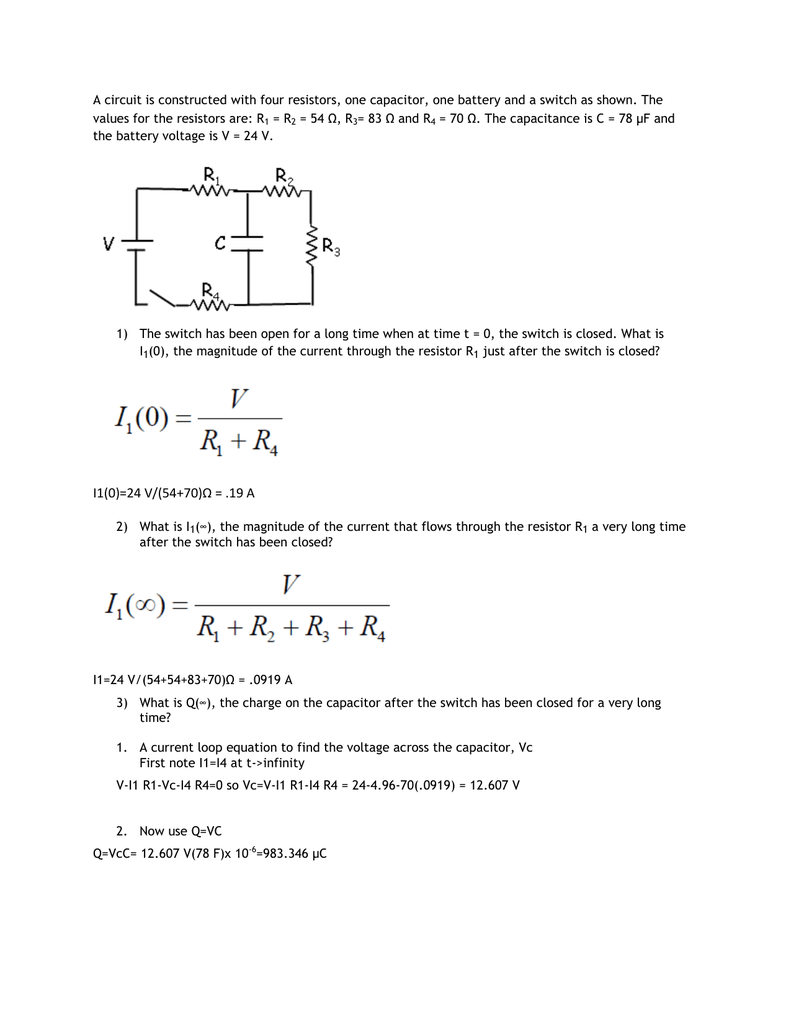
What Is The Current Flowing Through Resistor R1

Find Out The Current Flowing Through Resistor R1

Find Out The Current Flowing Through Resistor R1

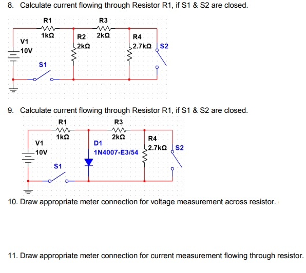
Solved 8 Calculate Current Flowing Through Resistor R1 Chegg Com

Solved 8 Calculate Current Flowing Through Resistor R1 Chegg Com

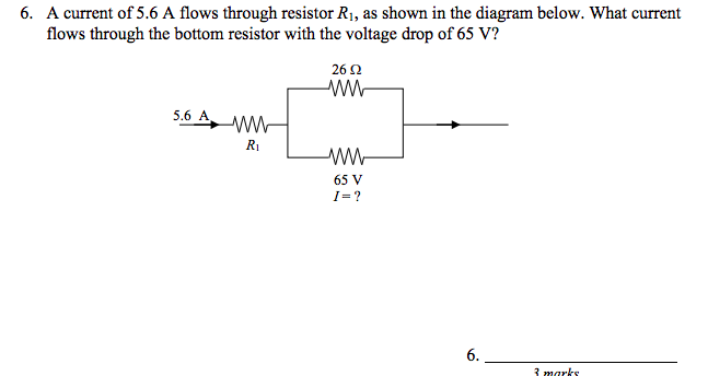
Solved 6 A Current Of 5 6 A Flows Through Resistor R1 A Chegg Com

Solved 6 A Current Of 5 6 A Flows Through Resistor R1 A Chegg Com

Description This Is Perhaps One Of The Simplest Electronic Fuse Circuit One Can Make The Circu Electronics Circuit Simple Electronic Circuits Circuit Diagram

Description This Is Perhaps One Of The Simplest Electronic Fuse Circuit One Can Make The Circu Electronics Circuit Simple Electronic Circuits Circuit Diagram

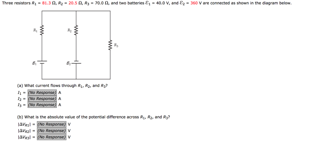
Solved Three Resistors R1 81 3 W R2 20 5 W R3 70 0 W Chegg Com

Solved Three Resistors R1 81 3 W R2 20 5 W R3 70 0 W Chegg Com

Calculate The Current Flowing Through The Resistor R1 In The Given Circuit R1 10w R2 20w And R3 30w Sarthaks Econnect Largest Online Education Community

Calculate The Current Flowing Through The Resistor R1 In The Given Circuit R1 10w R2 20w And R3 30w Sarthaks Econnect Largest Online Education Community

Calculate The Current Flowing Through The Resistor R1 In The Given Circuit R1 10w R2 20w And R3 30w Sarthaks Econnect Largest Online Education Community

In a parallel circuit the current flows across each path available to it.

What is the current flowing through resistor r1. Next you need itotal using ohms law v ir. Current flowing in r 1 v s r 1 12v 22kω 0 545ma or 545μa. Now what is the current flowing through resistor r1. I2 v r 2 24 20 1 2 a.

Thus current total of resistors must be equal to total current. Think about how the current flows. So by closing this switch you re essentially removing r2 from the circuit. In the following example the resistors r 1 r 2 and r 3 are all connected together in series between points a and b with a common current i flowing through them.

I1 2xi1 3xi1 3a. A 24 v power source and three resistors are connected in series with r 1 4 ω r 2 2 ω and r 3 6 ω. Current flowing in r 2 v s r 2 12v 47kω 0 255ma or 255μa. Now that value is in series with r1 so rtotal r1 4 8 8 4 8 12 8ohm.

You need to calculate the total resistance if the circuit first to figure out the total current flowing through r1. And use the exact same technique. Similarly if i2 is the current flowing through the resistor r2 thenaccording to ohm s law. Current will flow through the wire on the left cross the left resistor and reach the other end.

If i3 is the current flowing through the resistor r3 thenaccording to ohm s law. Well these lines where we see no resistors in circuit diagrams that s assumed to be resistance less so all of the current will actually flow that way. But we can keep analyzing it. Then by using ohm s law the current flowing through each resistor of example no2 above can be calculated as.

I3 v r 3 24 30. Current sources must flow their electrons on resistors eventually. If i1 is the current flowing through the resistor r1 then according to ohm s law. Thereby if the current that flows through r2 is to be i1 then current of r1 would be 2xi1.

The current will just go through r1 and then follow the path of least resistance literally. Calculate the current in the circuit which is the same across each resistor since there is only one wire in the circuit. At the same time current will flow through the wire on the right cross the right resistor and reach the end. Suppose the voltage source provides a potential difference voltage difference of 7 00 v.

I t i r1 i r2. Thus the total current flowing in the circuit is given as. And one thing that you should feel very comfortable of is that this current that is flowing through the first resistor that four ampere current that current gets split between i two and i three. Then the amount of current that flows through a set of resistors in series will be the same at all points in a series resistor network.

For fun i encourage you to figure out what that current is now the current i sub three. In this case when finding the total current flowing from the battery you need to consider the overall or equivalent resistance of the circuit. R2 and r3 are in parallel so their combined resistance is r2 r3 r2 r3 4 8ohm.

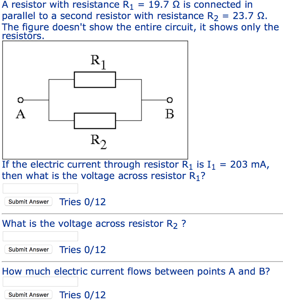
Solved A Resistor With Resistance R1 19 7 Is Connecte Chegg Com

Solved A Resistor With Resistance R1 19 7 Is Connecte Chegg Com

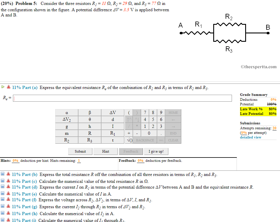
Solved 20 Problem 5 Consider The Three Resistors R1 1 Chegg Com

Solved 20 Problem 5 Consider The Three Resistors R1 1 Chegg Com

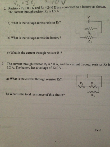
Solved Resistors R 1 8 0 Ohm And R 2 24 0 Ohm Are Con Chegg Com

Solved Resistors R 1 8 0 Ohm And R 2 24 0 Ohm Are Con Chegg Com

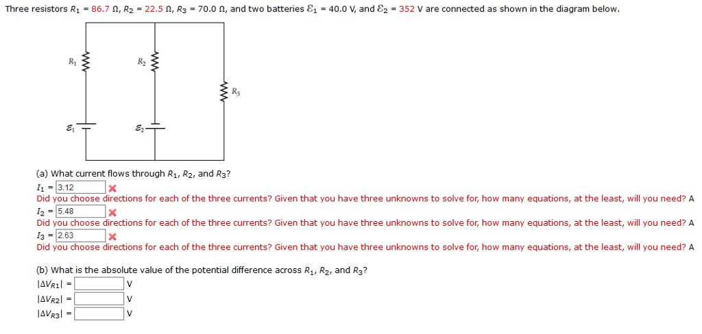
Solved Three Resistors R1 86 7 W R2 22 5 W R3 70 Chegg Com

Solved Three Resistors R1 86 7 W R2 22 5 W R3 70 Chegg Com

Protected Blog Log In Electrical Circuit Diagram Ldr Light Circuit

Protected Blog Log In Electrical Circuit Diagram Ldr Light Circuit

Ring Oscillator Schematic Using 3 2n3904 Npn Transistor Inverter Circuits In 2020 Transistors Electronics Circuit Circuit

Ring Oscillator Schematic Using 3 2n3904 Npn Transistor Inverter Circuits In 2020 Transistors Electronics Circuit Circuit

Howland Current Pump Circuit Electronics Circuit Circuit Circuit Diagram

Howland Current Pump Circuit Electronics Circuit Circuit Circuit Diagram

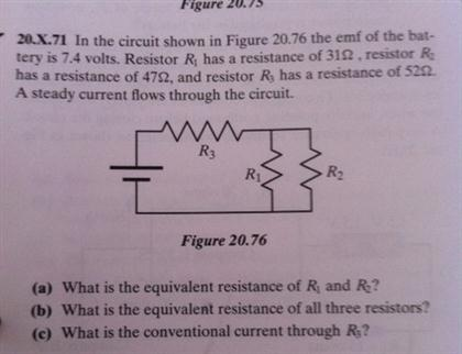
Solved In The Circuit Shown In Figure 20 76 The Emf Of Th Chegg Com

Solved In The Circuit Shown In Figure 20 76 The Emf Of Th Chegg Com

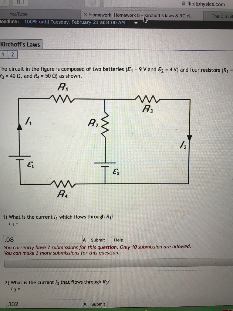
Solved The Circuit In The Figure Is Composed Of Two Batte Chegg Com

Solved The Circuit In The Figure Is Composed Of Two Batte Chegg Com

Solved Draw A Diagram Including The Three Resistors R1 Chegg Com

Solved Draw A Diagram Including The Three Resistors R1 Chegg Com

Rc Circuits

Rc Circuits

A Resistor Is An Electrical Component That Implements Electrical Resistance As A Circuit Element Electricity Can No Speaker Projects Cool Pictures Electricity

A Resistor Is An Electrical Component That Implements Electrical Resistance As A Circuit Element Electricity Can No Speaker Projects Cool Pictures Electricity

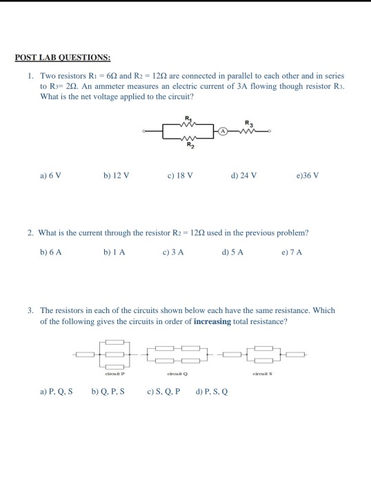
Solved Ns 1 Two Resistors R1 6w And R2 12w Are Connected Chegg Com

Solved Ns 1 Two Resistors R1 6w And R2 12w Are Connected Chegg Com

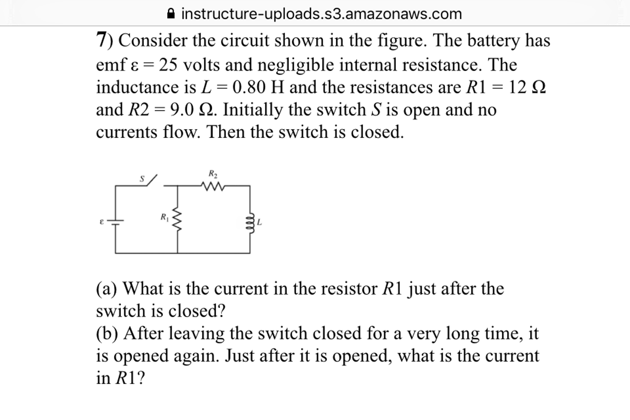
Solved Consider The Circuit Shown In The Figure The Batt Chegg Com

Solved Consider The Circuit Shown In The Figure The Batt Chegg Com

Source : pinterest.com