Voltage Regulation Vs Power Factor Graph

Ideal Voltage Transfer Curve The Ideal Op Amp Produces The Output Proportional To The Difference Between The Two Input Voltages The Graph Transfer Curve Ideal

Ideal Voltage Transfer Curve The Ideal Op Amp Produces The Output Proportional To The Difference Between The Two Input Voltages The Graph Transfer Curve Ideal

Ac Waveform Ac Circuit Theory Circuit Theory Ac Circuit Sine Wave

Ac Waveform Ac Circuit Theory Circuit Theory Ac Circuit Sine Wave

Phasor Diagram Of Synchronous Generator Phasor Diagram Of Alternator Diagram Alternator Generation

Phasor Diagram Of Synchronous Generator Phasor Diagram Of Alternator Diagram Alternator Generation

Voltage Regulation Of Transformer Electrical4u

Voltage Regulation Of Transformer Electrical4u

Graph Of Variation Of Output Voltage Against Distance Between Terminals Download Scientific Diagram

Graph Of Variation Of Output Voltage Against Distance Between Terminals Download Scientific Diagram

Voltage Regulation Of Alternator By Emf Method And Solved Problem Ruse Alternator Method

Voltage Regulation Of Alternator By Emf Method And Solved Problem Ruse Alternator Method

Voltage Regulation Of Alternator By Emf Method And Solved Problem Ruse Alternator Method

It is clear that with change in load there is a change in terminal voltage of an alternator.

Voltage regulation vs power factor graph. First of all voltage regulation is one of the figure of merits like efficiency from which performance of electrical machines can be judged. It is commonly used in power engineering to describe the percentage voltage difference between no load and full load voltages distribution lines transmission lines and transformers. Power factor correction and voltage regulation are closely related. What is voltage regulation.

Voltage regulation of transformer at unity power factor. It depends upon the power factor of the load. Output power factor remains in the range of 0 96 or higher from half to full load. The voltage regulation of an alternator is defined as the rise in voltage when full load is removed field excitation and speed remaining the same divided by the rated terminal voltage.

Voltage regulation of a synchronous generator the voltage regulation of a synchronous generator is the rise in voltage at the terminals when the load is reduced from full load rated value to zero speed and field current remaining constant. The magnitude of this change depends not only on the load but also on the load power factor. For unity and lagging power factors there is always a voltage drop with the increase of load but for a. Where i is the full load secondary current and v 2 the full load secondary voltage equal to the value of v 2 rated.

In many cases the desired voltage regulation is costly to obtain. Explanation of voltage regulation of transformer. A ferroresonant transformer can operate with an input voltage range 40 or more of the nominal voltage. Larger or paralleled conductors to reduce voltage drop under load are in many cases the proper solution.

Figure 3 a shows a phasor diagram for the case of a resistive load unity power factor on the transformer i e the load current is in phase with the secondary voltage. A voltage regulator is a system designed to automatically maintain a constant voltage level. Voltage regulation is a measure of change in the voltage magnitude between the sending and receiving end of a component. Voltage regulation at a unity b lagging c leading power factor.

Voltage regulation is a measure of change in the voltage magnitude between the sending and receiving end of a component such as a transmission or distribution line. As follows the graph of efficiency vs output power is given below 4. Graph of voltage output on a time scale.

Basic Knowledge Of Voltage Regulator 2 4 Your Analog Power Ic And The Best Power Management Torex

Basic Knowledge Of Voltage Regulator 2 4 Your Analog Power Ic And The Best Power Management Torex

Advantages Of Rotating Field Over Rotating Armature In Alternator Electrical Machines 2 Alternator Electricity Rotating

Advantages Of Rotating Field Over Rotating Armature In Alternator Electrical Machines 2 Alternator Electricity Rotating

3 Phase Motorcycle Voltage Regulator Circuit Homemade Circuit Projects Circuit Homemade Motorcycle Voltage Regulator Circuit Projects Circuit Design

3 Phase Motorcycle Voltage Regulator Circuit Homemade Circuit Projects Circuit Homemade Motorcycle Voltage Regulator Circuit Projects Circuit Design

103 Questions With Answers In Capacitance Voltage Scientific Method

103 Questions With Answers In Capacitance Voltage Scientific Method

Constant Current Vs Constant Voltage Output

Constant Current Vs Constant Voltage Output

Terminal Voltage Per Phase Armature Current Characteristic Download Scientific Diagram

Terminal Voltage Per Phase Armature Current Characteristic Download Scientific Diagram

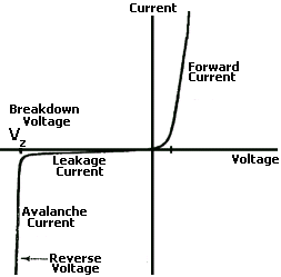
What Are The Characteristics Of A Zener Diode As A Voltage Regulator Quora

What Are The Characteristics Of A Zener Diode As A Voltage Regulator Quora

Does The Capacitance Change When A Dc Voltage Is Applied To Ceramic Capacitors Are There Any Points To Be Aware Of Regarding Changes In The Capacitance Murata Manufacturing Co Ltd

Does The Capacitance Change When A Dc Voltage Is Applied To Ceramic Capacitors Are There Any Points To Be Aware Of Regarding Changes In The Capacitance Murata Manufacturing Co Ltd

Pole Pitch In Electrical Machines Slot Angle Short Pitch And Full Pitch Winding In Alternator Alternator Electricity Slot

Pole Pitch In Electrical Machines Slot Angle Short Pitch And Full Pitch Winding In Alternator Alternator Electricity Slot

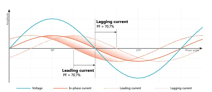
Power Factor Pf Cos F

Power Factor Pf Cos F

Electrical Marine Engineer

Electrical Marine Engineer

Dc To Dc Converter Smps Block Diagram Block Diagram Switched Mode Power Supply Step Down Transformer

Dc To Dc Converter Smps Block Diagram Block Diagram Switched Mode Power Supply Step Down Transformer

Output Voltage And Current For Firing Angle A The Gate Pulse Given To Download Scientific Diagram

Output Voltage And Current For Firing Angle A The Gate Pulse Given To Download Scientific Diagram

Switch On Delay Timer Circuit Circuitspedia Circuit Diagram Electronic Schematics Timer

Switch On Delay Timer Circuit Circuitspedia Circuit Diagram Electronic Schematics Timer

Source : pinterest.com