Voltage Divider Explained
It provides a simple formula to calculate the voltage across a resis.
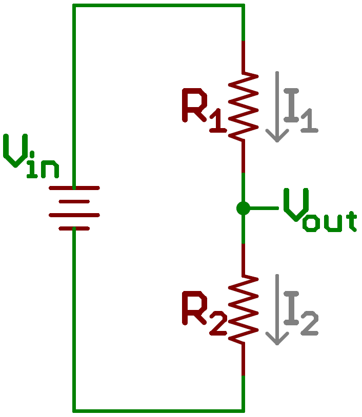
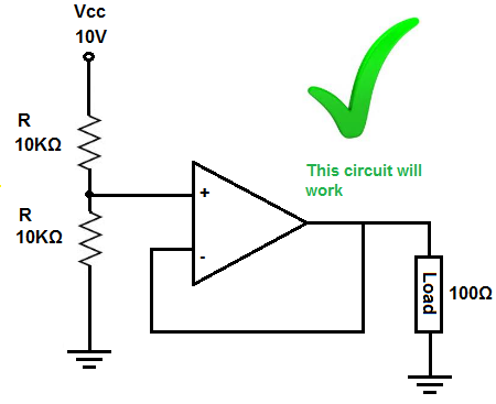
Voltage divider explained. The current division rule determines the current across the circuit impedance. As explained above a voltage divider circuit can be built using a couple of resistors in different forms as given below. If the current in the output wire is zero. Each potential divider circuit has two resistors connected in series.
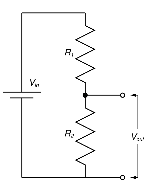
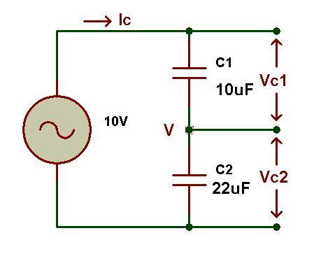
It s output voltage is a fixed fraction of its input voltage. The voltage divider rule is used to solve circuits to simplify the solution applying this rule can also solve simple circuits thoroughly the main concept of this voltage divider rule is the voltage is divided between two resistors which are connected in series in direct proportion to their resistance. The input voltage is applied across the series impedances z 1 and z 2 and the output is the voltage across z 2 z 1 and z 2 may be composed of any combination of elements such as resistors inductors and capacitors. Circuit of voltage divider.
To best explain the voltage divider circuit or potential divider circuit i made three potential divider circuits in proteus simulation software. A parallel circuit acts as a current divider as the current divides in all the branches in a parallel circuit and the voltage remains the same across them. Written by willy mcallister. The resistors r1 r3 and r5 are 10k resistors while the resistor r2 1k r4 2k and r6.
The current division is explained with the help of the circuit shown below. Using just two series resistors and an input voltage we can create an output voltage that is a fraction of the input. Voltage divider rule voltage divider rule. The grove voltage divider provides an interface for measuring external voltage which eliminates the need to connect a resistance to input interface.
A voltage divider referenced to ground is created by connecting two electrical impedances in series as shown in figure 1. In the above shown diagrams a signifies shorthand b demonstrates longhand and c and d represents the resistor connections with elaborate details. A voltage divider is a simple circuit which turns a large voltage into a smaller one. The divide down ratio is determined by two resistors.
This physics video tutorial provides a basic introduction into voltage divider circuits. Most sensors are simple resistive devices like our grove infrared reflective sensor. Voltage dividers are one of the most fundamental circuits in electronics.


