Voltage Clamp Graph Explained

In contrast the individual currents flowing during the complicated voltage change of the action potential cannot be measured experimentally but can only be calculated as neuron is doing here.
Voltage clamp graph explained. Using the voltage clamp controller and hodgkin huxley simulation model you created collect the data indicated in the table below by applying the bump test and equation 29. Voltage clamp is fundamentally different from the current clamp since it enables control of the membrane voltage of the cell. The patch clamp technique is a laboratory technique in electrophysiology used to study ionic currents in individual isolated living cells tissue sections or patches of cell membrane the technique is especially useful in the study of excitable cells such as neurons cardiomyocytes muscle fibers and pancreatic beta cells and can also be applied to the study of bacterial ion channels in. A basic voltage clamp will iteratively measure the membrane potential and then change the membrane potential voltage to a desired value by adding the necessary current.
In this article the working of a clamping circuit is explained. The voltage is normally stepped to a family of levels matching preset command patterns and the current supplied or absorbed by the circuit to hold the voltage at each level is measured. The working of different clamping circuits like positive and negative clamper with circuit diagrams and waveforms are given below. Voltage clamp protocol is used to study a minute patch of neuronal membrane sealed to the end of glass pipette by measuring the current.
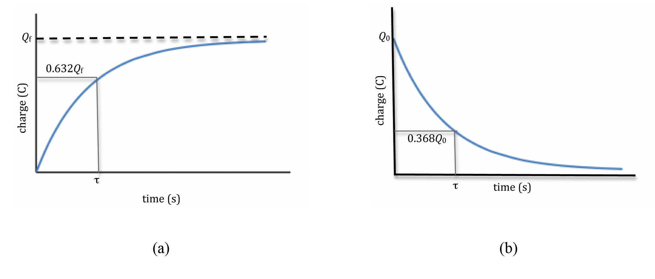
The time constant will be the difference in time from the start of the reference signal to the time at which the current achieves the value predicted by equation 29. The voltage clamp is a technique used to control the voltage across the membrane of a small or isopotential area of a nerve cell by an electronic feedback circuit. The value ie time course of the membrane voltage is specified by the experimentalist called command voltage v cmd and the circuit in the amplifier injects the required current to counteract any change to the membrane voltage that would occur without the voltage clamp. The voltage clamp measures currents in response to the relatively simple stimulus of a voltage step a paradigm we will explore in the next simulation.
This method was the best basic biophysical technique used for studying the ion channels. Now the feedback loop in the voltage clamp amplifier has to pass an equal and opposite current to clamp the voltage at the new set potential. The output voltage will be the sum of the input voltage and the capacitor voltage and is equal to v v v 0 or 2 v v 0. The voltage clamp is an experimental method used by electrophysiologists to measure the ion currents through the membranes of excitable cells such as neurons while holding the membrane voltage at a set level.
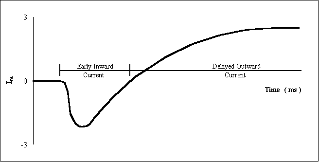
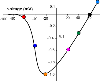
There are some important conventions that you need to know to be able to read voltage clamp records. Using the voltage clamp one can step the membrane to different voltages and measure the current flows through the membrane over time at that fixed voltage.


