Voltage Clamp Experiment Explained

How Exactly Does Current And Voltage Clamping Work

How Exactly Does Current And Voltage Clamping Work

What Is The Voltage Clamp Method Molecular Devices

What Is The Voltage Clamp Method Molecular Devices

4 Active Behavior Of The Cell Membrane

4 Active Behavior Of The Cell Membrane

The Voltage Clamp Method Youtube

The Voltage Clamp Method Youtube

Voltage Clamp An Overview Sciencedirect Topics

Voltage Clamp An Overview Sciencedirect Topics

Types Of Clipper And Clamper Circuits And Its Working With Applications Circuit Positivity Type

Types Of Clipper And Clamper Circuits And Its Working With Applications Circuit Positivity Type

Types Of Clipper And Clamper Circuits And Its Working With Applications Circuit Positivity Type

Now the feedback loop in the voltage clamp amplifier has to pass an equal and opposite.

Voltage clamp experiment explained. The voltage clamp technique allows an experimenter to. Na v 1 5 was overexpressed using the adenoviral ad construct ad na v 1 5 5. The voltage clamp is an experimental method used by electrophysiologists to measure the ion currents through the membranes of excitable cells such as neurons while holding the membrane voltage at a set level. Explained step by.

A control group of myocytes was infected with an adenoviral construct encoding green fluorescence protein ad gfp. Basic voltage clamp experiments 3 1 capacitive and voltage dependent currents during a voltage clamp pulse go to the voltage clamp lab with click on the voltage clamp button. Voltage clamp experiments presented in figure 21 1 show a reciprocal regulation of na v 1 5 and kir2 1 in adult rat ventricular myocytes arvms. I guess it really depends on each type of experiments but some basic type of.

The patch clamp technique is a laboratory technique in electrophysiology used to study ionic currents in individual isolated living cells tissue sections or patches of cell membrane the technique is especially useful in the study of excitable cells such as neurons cardiomyocytes muscle fibers and pancreatic beta cells and can also be applied to the study of bacterial ion channels in. The working of different clamping circuits like positive and negative clamper with circuit diagrams and waveforms are given below. The output voltage will be the sum of the input voltage and the capacitor voltage and is equal to v v v 0 or 2 v v 0. In this article the working of a clamping circuit is explained.

The voltage is normally stepped to a family of levels matching preset command patterns and the current supplied or absorbed by the circuit to hold the voltage at each level is measured. The voltage clamp is a technique used to control the voltage across the membrane of a small or isopotential area of a nerve cell by an electronic feedback circuit. Now you will find a voltage pulse in the upper diagram which you can change in the same way as the current pulse in the current clamp lab. Why is there generation of action potentials at all.

To understand the classical voltage clamp experiments and to illustrate how these measurements were used to formulate the kinetics of voltage activated ion channels responsible for excitation na k fast gates slow gates etc. However many questions remain.

Voltage Clamp Youtube

Voltage Clamp Youtube

Infographic Electricity A Visual Cheat Sheet Gabetumblr Electronic Engineering Physics Electricity

Infographic Electricity A Visual Cheat Sheet Gabetumblr Electronic Engineering Physics Electricity

Voltage Clamp An Overview Sciencedirect Topics

Voltage Clamp An Overview Sciencedirect Topics

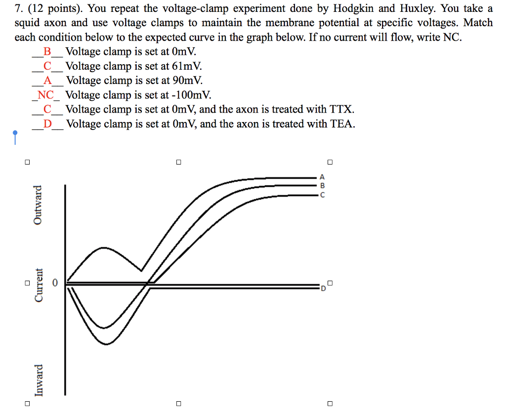
Solved 7 12 Points You Repeat The Voltage Clamp Exper Chegg Com

Solved 7 12 Points You Repeat The Voltage Clamp Exper Chegg Com

The Patch Clamp Technique Learn Share Leica Microsystems

The Patch Clamp Technique Learn Share Leica Microsystems

Lm340 Series Voltage Regulators And Its Types Voltage Regulator Regulators Electronics Circuit

Lm340 Series Voltage Regulators And Its Types Voltage Regulator Regulators Electronics Circuit

Clamp Multimeter How To Use For Dummies Electrical Gadgets Home Electrical Wiring Diy Electrical

Clamp Multimeter How To Use For Dummies Electrical Gadgets Home Electrical Wiring Diy Electrical

Ohm S Law Pie Chart Ohms Law Electrical Circuit Diagram Electronics Circuit

Ohm S Law Pie Chart Ohms Law Electrical Circuit Diagram Electronics Circuit

Common Rail Bosch Injector And Spare Parts Are Available Here Http Ift Tt 2mj0ie7 Common Rail Diesel Diesel Engine

Common Rail Bosch Injector And Spare Parts Are Available Here Http Ift Tt 2mj0ie7 Common Rail Diesel Diesel Engine

Untitled Document

Untitled Document

Pin De Sharon Wilson En Electronics En 2020 Circuito Electronico Electronica Diagrama Electronico

Pin De Sharon Wilson En Electronics En 2020 Circuito Electronico Electronica Diagrama Electronico

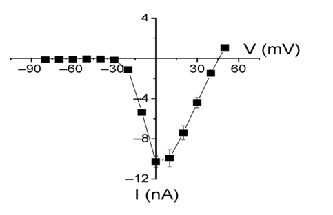
Consider The I V Relationships Shown Below From Da Chegg Com

Consider The I V Relationships Shown Below From Da Chegg Com

Electricity Water Analogy Google Search Ohms Law Free Energy Generator Electronic Circuit Projects

Electricity Water Analogy Google Search Ohms Law Free Energy Generator Electronic Circuit Projects

Voltage Level Indicator By Using Zenor Electronic Circuit Projects Circuit Electrical Circuit Diagram

Voltage Level Indicator By Using Zenor Electronic Circuit Projects Circuit Electrical Circuit Diagram

Source : pinterest.com