Software House Rm4 Wiring Diagram
Connect 12 or 24 vdc 5 to pin 2 of the power in connector.
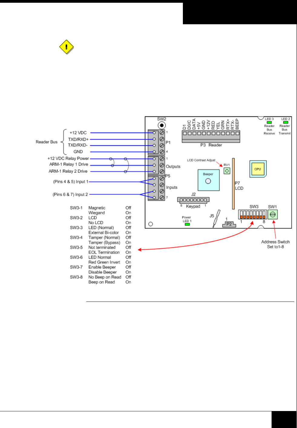
Software house rm4 wiring diagram. Point to point wiring diagrams consult with the acp installation documentation. In addition the rm 4 reader module provides two supervised inputs and two outputs and can be mounted in any suitable enclosure. Tm 4219 software house rm4 wiring diagram free rm 4 reader module installation sheet tyco safety rmxic proximity card hid iclass compatible user manual rm1 icp quick install rm4e start guide. Method a allows the circuitry to be powered with either 12 vdc or 24 vdc and also supplies battery charging power.
Rm 4 reader module installation sheet. Tm 4219 software house rm4 wiring diagram free. A wiring diagram is a streamlined conventional pictorial representation of an electrical circuit. The rm 4 reader module is a circuit board that creates the connectivity between a reader and an apc or istar controller when third party card readers are used on a c cure system.
Rm 4e power wiring method a method a via power in software house recommends method a for powering the circuitry. Symbols required for home wiring plan when you are going to make a wiring plan the built in symbol library contains the most commonly used wiring plan symbols including lighting switches sockets and some individual appliances such as ceiling fan doorbell smoke detector monitor and alarm a home wiring plan is usually created based on the. It reveals the parts of the circuit as simplified forms and also the power and signal links between the tools.


