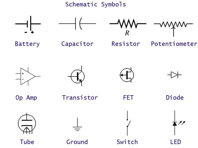
Schematic Symbol Of Ground

Digital common ground.
Schematic symbol of ground. I m also puzzled why the link to earth is shown on gnd rather than on pgnd. In addition to a common ground path most circuits also have a common voltage path. Signal ground it is a reference point from which the signal is measured. To see how the current flows in a circuit diagram with ground symbols just connect all the points that have ground symbols.
That is what you do when you build the circuit. Flow of current when the ground symbol is shown. In fact most schematic diagrams use ground symbols instead of a line to show the path by which current returns to the battery. Ground it is equivalent to theoretical 0v and is used as zero potential reference.
From this key it seems that various parts of the above circuit are to be. In this question is the following diagram for a voltage booster intended for small battery powered devices. Used for zero potential reference and electrical shock protection. In electrical engineering ground or earth is the reference point in an electrical circuit from which voltages are measured a common return path for electric current or a direct physical connection to the earth.
Electrical symbols electronic circuit symbols of schematic diagram resistor capacitor inductor relay switch wire ground diode led transistor power. Electrical ground symbols of circuit diagram earth ground chassis ground digital ground. Exposed metal parts of electrical equipment are connected to ground so that failures of internal. An example circuit using ground symbols.
The common voltage path goes from the battery to the resistor and on to the second transistor. The tps61200 spec says gnd is control logic ground and pgnd is power ground but this isn t reflected in the symbols chosen in the diagram. Connected to the chassis of the circuit.


