Nema Schematic Symbols

A diagram made up of a group of interconnected blocks each of which represents a device or.
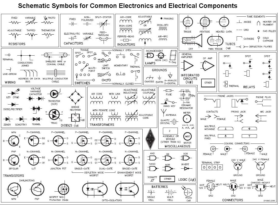
Nema schematic symbols. The following tables describe the device and show the symbol by area of usage. It shows the parts of the circuit as simplified shapes and also the power and signal connections in between the tools. Ics 19 2002 page 1 guide for diagrams devices designations and symbols for industrial controls and systems 1 general information 1 1 scope the scope of this document is to provide guidelines for representation of devices on diagrams and drawings in a standardized manner. The purpose of this document is to provide a simple cross reference of common schematic wiring diagram symbols used throughout various parts of the world.
A wiring diagram is a streamlined standard photographic depiction of an electrical circuit. Physical relationships are usually disregarded. The electrical standards products guide lists nema standards product categories and the member manufacturers of those products. Disconnect circuit interrupter circuit breakers w thermal ol circuit breakers w magnetic ol limit switches foot switches pressure vacuum switches liquid level switches temperature actuated.
1 2 definitions block diagram. Espg is the guide to electrical products and is read by buyers specifiers contractors and distributors your client base. The diagram symbols in table 1 are used by square d and where applicable conform to nema national electrical manufacturers a ssociation standards. Graphic symbols the course of an electrical circuit or circuits and the component devices or parts used therein.
Electrical schematic nema iec electrical symbols comparison here below the cross reference of common schematic wiring diagram symbols used throughout various parts of the world. Variety of nema l5 30 wiring diagram.


