How Does Electricity Flow Through A Breadboard

It also helps to compare the flow of electricity through wires with the flow of.
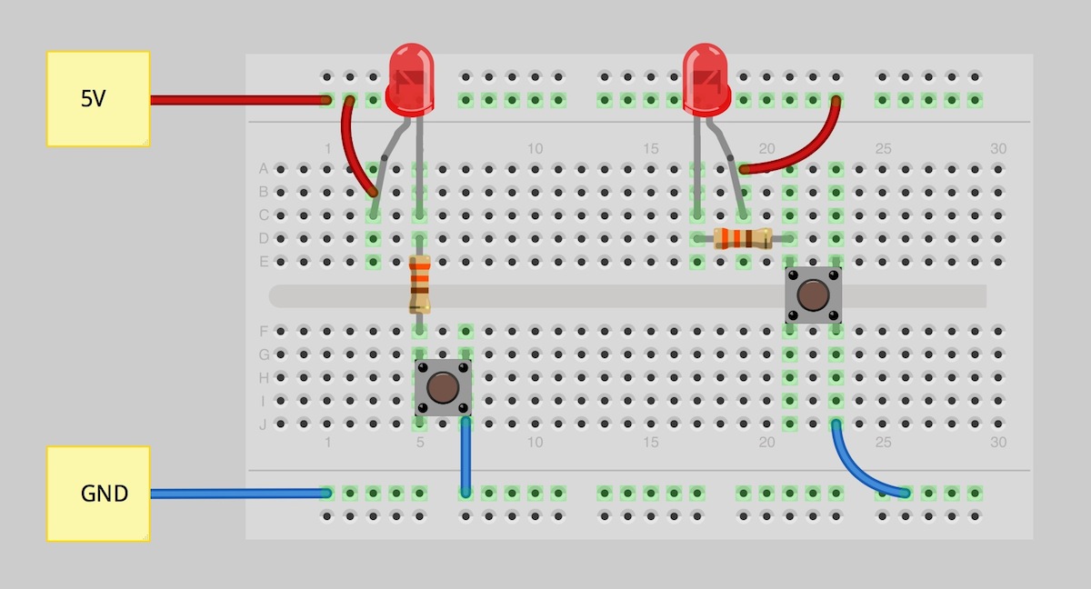
How does electricity flow through a breadboard. The current flows from the battery s positive terminal to the negative terminal. This means that at the top breadboard the current passes through the resistor then the current flows into the anode pin of the led flows through the led out the cathode pin and then returns to the batteries negative terminal there is no ground in this circuit. My question arises at the second breadboard at the bottom. See the advanced section to learn more breadboard diagrams make it easy for beginners to follow instructions to build a circuit because they are designed to look like the real thing.
The 2 rows of holes at either end are for power one for positive red one for negative black. Electricity will flow from a higher voltage to a lower voltage. A breadboard diagram is a computer generated drawing of a circuit on a breadboard. Wiring steps again disconnect power to your breadboard to avoid damaging your components press the 7 segment display into breadboard so the it straddles the center section of the board figure 1 connect one of the common cathode pins of the display pins 3 or 8 to ground figure 3 connect power across to the other side of the board figure 4 insert 7 current limiting resistors onto.
For most people electricity is a mysterious force that somehow magically appears when we flip a light switch or plug in an appliance. Electricity needs a path to flow through which must be an electrical conductor such as copper wire. The power strips go horizontally in 5 s where as the component strips go vertically. So from what i understand the electricity flows from the battery s positive terminal to the negative.
Open circuits are often created by design. Yet while the science behind the flow of electricity is very complex the basics of electrical flow or current are easy to understand if you learn some key terms and functions. So far so good. The water will flow for a short time but then stop when all the water exits the pipe.
As you can see i edited the picture below to give you an idea of how circuits are completed. What that means is the electricity has to flow through a closed circuit which is what will allow it to function as intended. Types of breadboards today s breadboards are made from all sorts of materials and they vary in size and shape as well. Dc voltage sources always have two sides called positive and negative with the positive side a higher voltage than the negative side.
I m kind of beating around your question mainly because i couldn t tell you how the current flows through the arduino. Unlike a circuit diagram or a schematic which use symbols to represent electronic components. As you can see from the image below a breadboard has lots of holes this may seem confusing at first but it really isnt. Picture a gallon of water flowing through an open pipe.
For a more solid reasoning of why look into integrated circuits vlsi very large scale integration and related topics that are sure to pop up in your search.


