Draw The Circuit Diagram For Experimental Verification Of Ohm S Law

Make a diagram of experimental verification of ohm s.
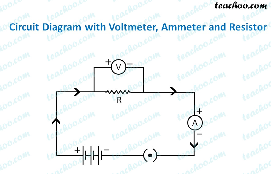
Draw the circuit diagram for experimental verification of ohm s law. What current will the heater draw if the potential difference is increased to 120 v. Take care to connect the ammeter and voltmeter with their correct. Where v is the voltage i is the current and r is the resistance. Draw the circuit diagram as shown above.
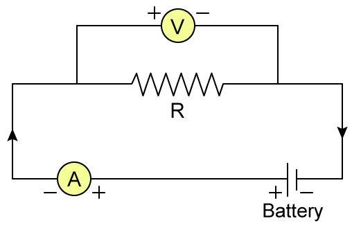
V i r. The circuit diagram to verify ohm s law is drawn below. Arrange the apparatus as per the circuit diagram. The above diagram is of the circuit used in the lab for verification of ohm s law.
Above the both diagrams are correct. Applying circuit rules for current and voltage with ohm s law allows us to formulate rules to determine total. Voltmeter across a resistor is connected in parallel. Experimental verification of ohm s law.
View answer in the circuit shown below current l 0 flowing through 6 ω resistance and voltage drop v 0 across 3 ω resistance respectively are. Circuit diagram to show experimental set up for verification of ohm s law is shown below. Arrange the apparatus as per the circuit diagram. Clean the ends of the connecting wires with sand paper and make them shiny.
Formula v i r where r is constant of proportionality called resistance. At constant temparature the current flowing through a conductor is directly proportional to the potential difference across its ends. Clean the ends of the connecting wires with sand paper and make them shiny. Make the connections as per circuit diagram.
Ohm s law states that current through a conductor is directly proportional to voltage difference across it. Q draw a circuit diagram to show experimental set up for verification of ohm s law. Ohm s law relates the resistance of a component to its voltage and current. Draw the circuit diagram as shown above.
All connections must be neat and tight.


