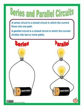
Current Flow In A Series Circuit

Series And Parallel Circuits Series And Parallel Circuits Electrical Projects Circuit

Series And Parallel Circuits Series And Parallel Circuits Electrical Projects Circuit

How Simple Series Circuit Works Electronics Projects Circuits Simple Electronic Circuits Circuit Electronics Projects

How Simple Series Circuit Works Electronics Projects Circuits Simple Electronic Circuits Circuit Electronics Projects

Electrical Circuit Chart Science Notes Electricity Lessons Science Electricity

Electrical Circuit Chart Science Notes Electricity Lessons Science Electricity

How Simple Series Circuit Works Simple Electronic Circuits Electronics Projects Electronic Schematics

How Simple Series Circuit Works Simple Electronic Circuits Electronics Projects Electronic Schematics

How Simple Series Circuit Works Electronics Projects Circuits Simple Electronic Circuits Circuit Circuit Diagram

How Simple Series Circuit Works Electronics Projects Circuits Simple Electronic Circuits Circuit Circuit Diagram

Series And Parallel Circuits Guided Notes And Worksheets This Product Consists Of The Following Series And Parallel Circuits Electricity Lessons Circuit

Series And Parallel Circuits Guided Notes And Worksheets This Product Consists Of The Following Series And Parallel Circuits Electricity Lessons Circuit

Series And Parallel Circuits Guided Notes And Worksheets This Product Consists Of The Following Series And Parallel Circuits Electricity Lessons Circuit

One from 1 to 2 to 5 to 6 and back to 1 again and another from 1 to 2 to 3 to 4 to 5 to 6 and back to 1 again.

Current flow in a series circuit. An ammeter measures current and a voltmeter measures a potential difference. A series circuit forms a pathway that has only one loop therefore the current flowing through components is the same and the voltage divides depending on the resistance of each component. A circuit that has only one path for current flow is a circuit. The same current flows through each part of a series circuit in a series circuit the amperage at any point in the circuit is the same.

In series circuits the resistor with the greatest resistance has the greatest voltage drop. Some materials have low resistance and are conductors. A circuit is said to be a series circuit if the components are connected in a series configuration or cascaded formation in a single line. This is because there is only one path for current flow in a series circuit.

In this circuit we have two loops for the current to flow through. For example if even one of the light bulbs in an older style string of christmas tree lights burns out or is removed the entire string becomes inoperable until the bulb is replaced. A series circuit has only one path in which its current can flow. The elements are added consequently and in the same line.

What is the voltage across the other resistor. Because electric charge flows through conductors like marbles in a tube the rate of flow marble speed at any point in the circuit tube at any specific point in time must be equal. Once you have a basic idea of what a series circuit connection involves you can learn how to calculate total current. The voltage across o e resistor is 40 v.

The total power in a circuit is equal to the sum of the used in all parts. This will help in calculating circuit values using ohm s law. We can have circuits that are a combination of series and parallel too. You will notice from the diagram that 1 amp continually flows through the circuit.

Since the current is everywhere the same within a series circuit the i value of δv i r is the same in each of the resistors of a series circuit. All electrons in that loop form one current. So the voltage drop δv will vary with varying resistance. The amount of current in a series circuit is the same through any component in the circuit.

If one bulb goes out they all go out. Circuit is one loop. Opening or breaking a series circuit at any point causes the entire circuit to open or stop operating. There is only one path wherein the electrons and charges can flow.

A two resistor series circuit has an applied voltage of 100 v.

Rules Of Series And Parallel Circuits Series And Parallel Circuits Dc Circuit Circuit

Rules Of Series And Parallel Circuits Series And Parallel Circuits Dc Circuit Circuit

In A Series Circuit The Current Is Only Able To Flow Through A Single Path In A Series Circuit The Current Is The Electric Circuit Circuit Ohms Law

In A Series Circuit The Current Is Only Able To Flow Through A Single Path In A Series Circuit The Current Is The Electric Circuit Circuit Ohms Law

Learning Electronics For Beginners With Easy Ways Circuit Electronic Schematics Electronics Projects

Learning Electronics For Beginners With Easy Ways Circuit Electronic Schematics Electronics Projects

Electronics For Absolute Beginners Chapter 3 Absolute Beginners Beginners Chapter

Electronics For Absolute Beginners Chapter 3 Absolute Beginners Beginners Chapter

Rules Of Series And Parallel Circuits Series And Parallel Circuits Series Parallel Circuit

Rules Of Series And Parallel Circuits Series And Parallel Circuits Series Parallel Circuit

Series And Parallel Circuits Series And Parallel Circuits Homeschool Science Elementary Science

Series And Parallel Circuits Series And Parallel Circuits Homeschool Science Elementary Science

Electric Current Flow Indicator Battery Charger Circuit Battery Charger Charger

Electric Current Flow Indicator Battery Charger Circuit Battery Charger Charger

Dancing Scientist Science Electricity Circuits Science Elementary Science Activities

Dancing Scientist Science Electricity Circuits Science Elementary Science Activities

How To Make A Current Flow Indicator Electronics Area Electronics Projects Electronics Circuit Flow

How To Make A Current Flow Indicator Electronics Area Electronics Projects Electronics Circuit Flow

Students Will Learn The Difference Between Series And Parallel Circuits With This Fun Craftivity The Science Electricity Learning Science Second Grade Science

Students Will Learn The Difference Between Series And Parallel Circuits With This Fun Craftivity The Science Electricity Learning Science Second Grade Science

Basic Terms In An Electric Circuit Engineering Notes Physics And Mathematics Electric Circuit

Basic Terms In An Electric Circuit Engineering Notes Physics And Mathematics Electric Circuit

Triac Symbol Construction Working With Application Circuits In 2020 Electronic Schematics Circuit Power Electronics

Triac Symbol Construction Working With Application Circuits In 2020 Electronic Schematics Circuit Power Electronics

Series And Parallel Circuit Series And Parallel Circuits Science Electricity Science Fair Board

Series And Parallel Circuit Series And Parallel Circuits Science Electricity Science Fair Board

Resistors In Series And Parallel Combination Example1 In The Following Circuit Calculate The Total Current It Taken From T Series Parallel Circuits Simple Electric Circuit Electric Circuit

Resistors In Series And Parallel Combination Example1 In The Following Circuit Calculate The Total Current It Taken From T Series Parallel Circuits Simple Electric Circuit Electric Circuit

Source : pinterest.com