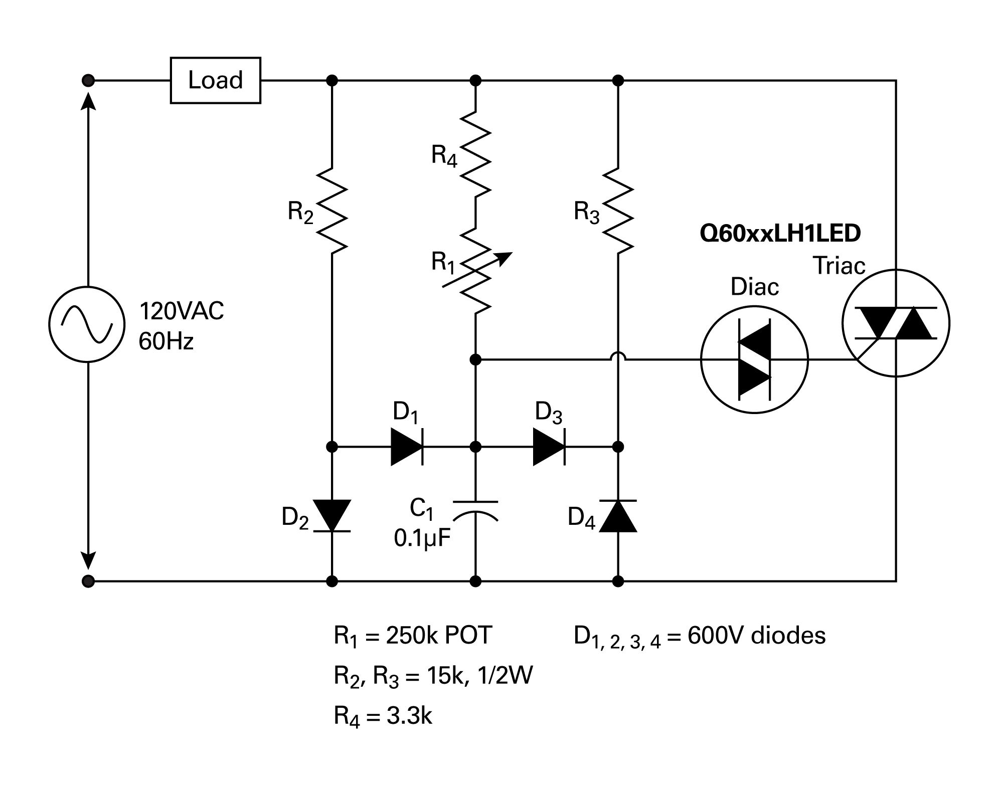
Current Circuit Diagram

As a physical quantity current is the rate at which charge flows past a point on a circuit.
Current circuit diagram. The total resistance of any series circuit is equal to the sum of the individual resistances. The green color indicates positive voltage. Yet current is a physical quantity that can be measured and expressed numerically. This is the circuit diagram.
This is an electronic circuit simulator. On this page we ll outline the three principles you should understand regarding series circuits. The moving yellow dots indicate current. The gray color indicates ground.
Circuit diagram is a free application for making electronic circuit diagrams and exporting them as images. These symbols represent the common electrical components. When three or more lines touch each other or cross each other and a node is placed at the intersection this represents the lines or wires being electrically connected at that point. A red color indicates negative voltage.
Experiment with an electronics kit. The schematic diagram represents the different components of a circuit. Some materials have low resistance and are conductors. A series circuit has only one path in which its current can flow.
Determine if everyday objects are conductors or insulators and take measurements with an ammeter and voltmeter. Circuit diagrams or schematic diagrams show electrical connections of wires or conductors by using a node as shown in the image below. For this circuit also the integrated circuit lm723 and electronic parts a few with follow the circuit appraise r1 11ohm for fix current at 60ma. We can seek the value r get from r 700 i and the transistor 2n3055 add keep for enlarge current the paramour at lm723 durable get make have the wastage of power to electricity work about 1 6watt only.
The supply voltage in a series circuit is equal to the sum of the individual voltage drops. The amount of current is the same through any component in a series circuit. Find the amount of electric charge that flows through the circuit. As depicted in the diagram below the current in a circuit can be determined if the quantity of charge q passing through a cross section of a wire in a time t can.
Design circuits online in your browser or using the desktop application. View the circuit as a schematic diagram or switch to a lifelike view. Build circuits with batteries resistors light bulbs fuses and switches. Series circuits are sometimes referred to as current coupled or daisy chain coupled the current in a series circuit goes through every component in the circuit.
An ammeter measures current and a voltmeter measures a potential difference. Therefore all of the components in a series connection carry the same current. To turn a switch on or off just click on it. Solved example for you.
A current of 0 75 a is drawn by the filament of an electric bulb for 10 minutes.


