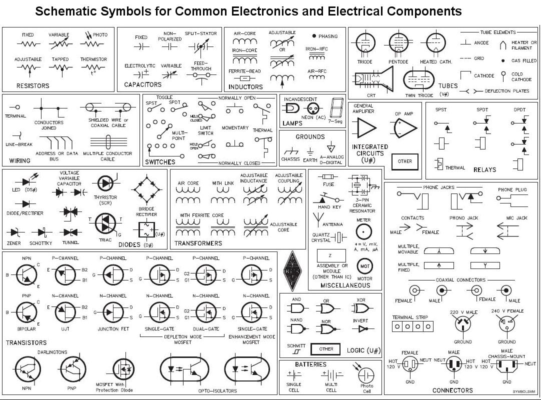
Common Schematic Symbols Used In Circuit Diagrams

Electrical symbols represent different components in electrical schematic block diagrams.
Common schematic symbols used in circuit diagrams. Electrical symbols electronic symbols. It might look fairly simple to most but it actually stands for three phase open delta grounded at common point. Note that when used. The standard circuit component symbols and circuit symbols are important for circuit schematic diagrams.
There are some standard symbols to represent the components in a circuits. The symbols are very important to represent electronic components in a circuit diagram without electronic symbol the design of circuit and schematics are very difficult and also knowing the components is very must to read the circuit diagram representation. Simple electronic circuits can have as little as two components. In electrical and electronics engineering we use different types of drawings or diagrams to represent a certain electrical system or circuit these electrical circuits are represented by lines to represent wires and symbols or icons to represent electrical and electronic components it helps in better understanding the connection between.
The symbols represent electrical and electronic components. Circuit symbols are used in circuit schematic diagrams which show how a circuit is connected together electrically. Later when you come across symbols you don t know you can come back here to identify what it is. Fortunately you need to know only a few basic symbols and labels to get you started.
There are hundreds of different types of electronic components and each has its own unique schematic diagram symbol. Below is an overview of the most used symbols in circuit diagrams. Symbols even more the electronic components have terminals and each will have its own name and polarities. Common automotive diagram symbols.
Electrical symbols and electronic circuit symbols are used for drawing schematic diagram. Most electronic circuits will have additional components. Each symbol in an electrical schematic has its purpose and is used to replace the need for what would otherwise be text heavy descriptions. This article gives some of the frequently used symbols for drawing the circuits.
The basic is passive and. There are many electrical and electronic schematic symbols are used to signify basic electronic or. An electronic symbol is a pictogram used to represent various electrical and electronic devices or functions such as wires batteries resistors and transistors in a schematic diagram of an electrical or electronic circuit these symbols are largely standardized internationally today but may vary from country to country or engineering discipline based on traditional conventions. A large and a small line is suppose to represent one battery cell so that the image below would suggest a two cell battery of 3 v.
Different types of electrical diagrams and drawing. A good example is the electrical symbol below. Standard circuit symbols for circuit schematic diagrams. Electrical symbols or electronic circuits are virtually represented by circuit diagrams.


