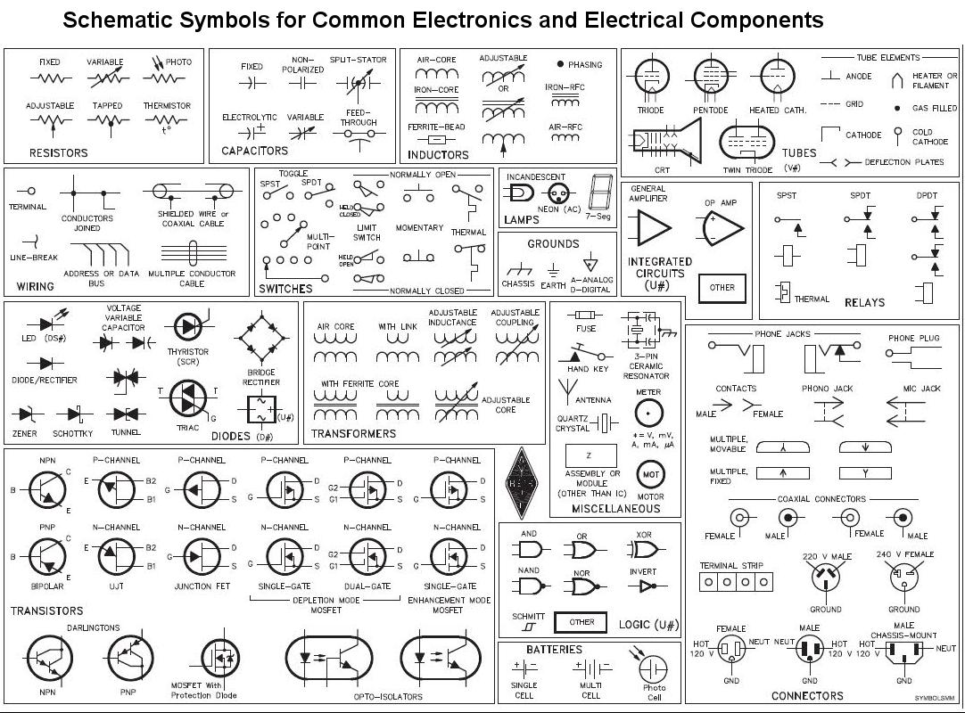
Circuit Diagram Using Standard Circuit Symbols

Electronic circuit symbols in electronic circuits there are many electronic symbols that are used to represent or identify a basic electronic or electrical device.
Circuit diagram using standard circuit symbols. It shows the relative positions of all the elements and their connections to one another. Scientists and engineers have developed a set of symbols to represent the components of an electric circuit. A circuit diagram electrical diagram elementary diagram electronic schematic is a graphical representation of an electrical circuit a pictorial circuit diagram uses simple images of components while a schematic diagram shows the components and interconnections of the circuit using standardized symbolic representations. Always begin by tracing its general shape that is a rectangle.
Choose from industry standard circuit diagram symbols our circuit drawing software lets you easily construct any type of circuit diagram with dedicated shape libraries. Circuit symbols are used in circuit schematic diagrams which show how a circuit is connected together electrically. 2 the standard symbols of the different electric components are located preferably in the middle of each side. 1 the diagram is drawn with a ruler and a pencil.
This makes it simpler to show how the various components of a circuit are wired together. Think of what we usually call a single battery. A final means of describing an electric circuit is by use of conventional circuit symbols to provide a schematic diagram of the circuit and its components. The presentation of the interconnections between circuit components in.
The standard circuit component symbols and circuit symbols are important for circuit schematic diagrams. Electric circuits can be described in a variety of ways. An electric circuit is commonly described with mere words like a light bulb is connected to a d cell. By using the various standard circuit symbols in schematic diagrams it is possible to create a diagram that is not only easy to read but also open to less mis interpretation than if non standard symbols are used.
A circuit diagram is a simplified representation of the components of an electrical circuit using either the images of the distinct parts or standard symbols. With dozens of industry standard shapes to choose from you can create schematics circuit diagrams wiring diagrams and other electrical diagrams. Another means of describing a circuit is to simply draw it. Most of the industrial standard circuit items can be changed in the appearance style and color according to the requirement.
We use circuit symbols to draw diagrams of electrical circuits with straight lines to show the wires. The diagram shows some common circuit symbols.


