Circuit Diagram For Experimental Verification Of Ohm S Law

You are very important to us.
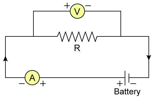
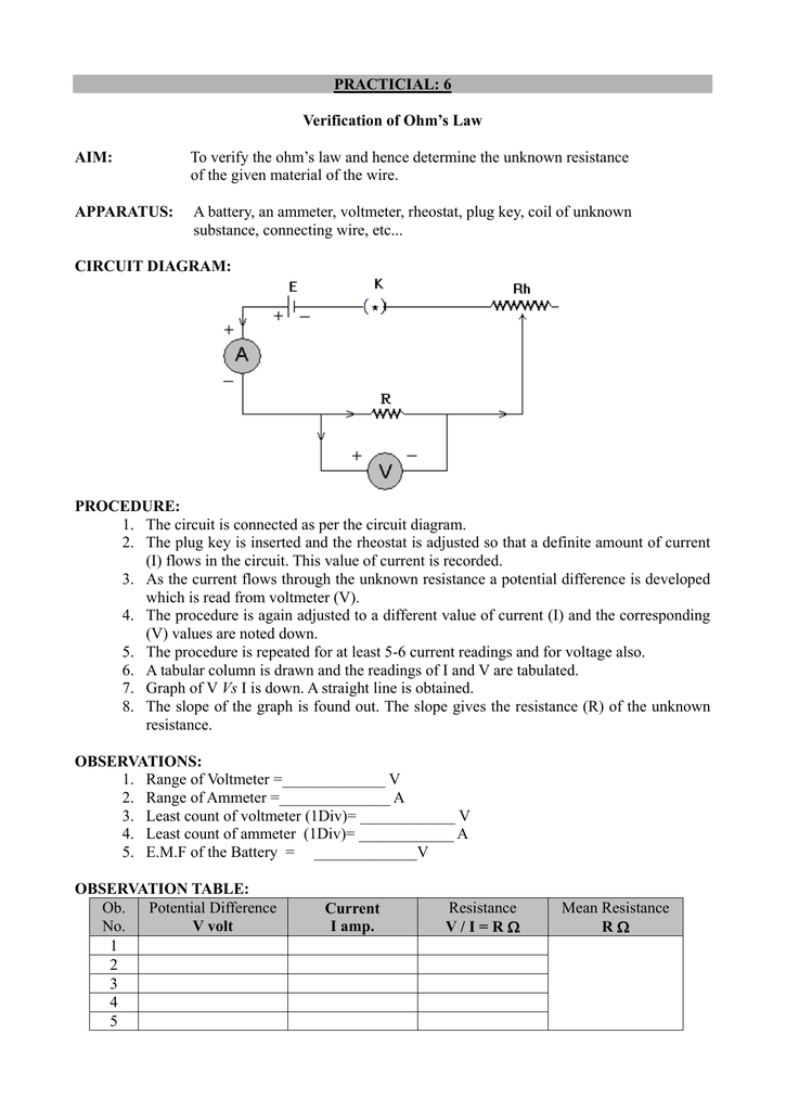
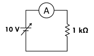
Circuit diagram for experimental verification of ohm s law. To study the dependence of potential difference v across a resistor on the current i passing through it and to determine its resistance. To determine the voltage resistance or current of an electric circuit. The following diagram will help you. Ncert books free download.
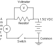
Ohm s law is also used in dc ammeter and other dc shunts to divert the current. Ts grewal class 11 accountancy solutions. B is the battery to supply the current to the circuit rh is rheostat to control the current in the circuit k is key to connect or break the circuit a is ammeter to measure the current in the circuit v is the voltmeter to measure the potential. For any content service related issues please contact on this number.
Ohm s law states that under constant temperature the current passing through conductor is directly proportional to potential difference applied across it. The above diagram is of the circuit used in the lab for verification of ohm s law. Also plot a graph between v and i. Ohm s law is used to maintain the desired voltage drop across the electronic components.
Limitations of ohm s law. Ohm s law relates the resistance of a component to its voltage and current. Express which of the following setups can be used to verify ohm s law. Ts grewal class 12 accountancy solutions.
Mon to sat 10 am to 7 pm.
